The cascade wind tunnel
This wind tunnel was designed in the Institute of Thermomechanics, and manufactured by ŠKODA Turbine factory in Pilsen. It was made operational in 1965. The tunnel is quite a unique facility, in which all types of turbine and axial compressor 2D blade cascades can be tested in a wide range of inlet angles and velocities – the range of Mach numbers both at inlet and outlet is 0.2 < M < 2, including the very tricky and problematic range of M ~ 1.
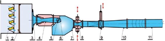 |
| Schematic of the tunnel |
Air enters through a silica gel dryer 1 and the pebble and cloth filters 2 into the inlet chamber, from which it passes into the entrance nozzle 3 and the supersonic inlet nozzle 4 into the rotatable test section 6. The entrance part of the test section can be adapted to required adjustment angle of cascade by adjusting device 5. The air exiting from the tested cascade flows into the settling chamber 7, and then through control nozzle 8, quick-acting valve 9, diffuser 10, main duct 11 to the vacuum storage.
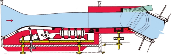 |
| Schematic of the inlet nozzle and test section |
The inlet nozzle and the test section have parallel side walls, the width of both being 160 mm. The nozzle height can be set within the range from 250mm to 450mm, according to the stagger angle, or the required inlet angle, of the cascade tested. The nozzle is designed so that for any height and required inlet Mach number it gives homogeneous, shock-less flow field at the cascade inlet, in the full range of Mach numbers from M = 1 (parallel walls) to M = 2 (Foelsch-type nozzle). The nozzle is symmetric, the lower and the upper walls are made of elastic steel sheets, and are set into the precalculated shape by a system of suspensions controlled by cams and rods. The whole setting is controlled from one common point for each wall.
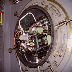
The test section is rotable within 180 degrees. The cascades tested are fixed into the side walls with the exit into the settling chamber. Depending on the shape and thickness of the blades, they have a chord from about 80 to 200mm. The full cascade is composed of two parts in which the blades are fixed to a steel strip so that the middle interblade channel is left free for optical measurements. Pneumatic measurements (traversing) behind the cascade requires free access in the side wall for the traversing probe, so that the traversing mechanism placed on the side wall has to be airtightly closed by a cover apparent in figure on the left below. Measurements at transonic velocities usually require a porous ventilated insert to the upper wall to prevent reflection of the system of front shock waves into the test section. A similar porous (perforated) wall can be placed behind the cascade with a similar effect, i.e., preventing reflection of the exit shock waves into the cascade exit field. Flaps at the exit nozzle can be used for fine control of the back pressure.
 |
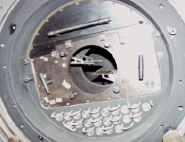 |
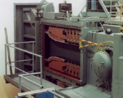
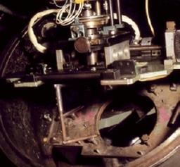
| View into the supersonic inlet nozzle, side wall removed | View into the rotatable test section |
Next to this wind tunnel is an auxiliary ejector (an induction type wind tunnel), also attached to the vacuum storage. Its sole function is to remove the air at transonic experiments from the plenum chamber of the ventilated walls.
Mach-Zehnder interferometer
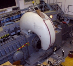 |
| Interferometer hanged above the tunnel |
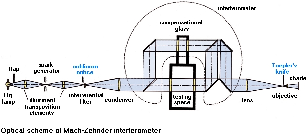 |
| Optical scheme of Mach-Zehnder interferometer |
Traversing device
Traverzing device is used for measuring the losses in cascades. It was designed and manufactured in the Institute of Thermomechanics CAS in 1965. It has a five-hole conical probe automatically turned into the direction of the exit velocity vector, while moving over two pitches behind the cascade. From the measured values of total pressure, static pressure, and the flow angle the loss coefficient and all the other exit flow parameters are evaluated on-line.
 |
 |
| Traversing device with the five hole probe | The traversing device |
| content: | Martin Luxa |
| designer & administrator: | David Šimurda |