Technological and service facilities of the laboratory
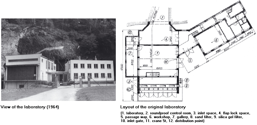
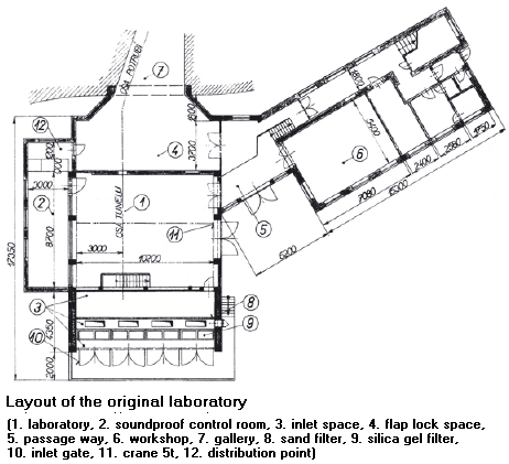
After extending the Laboratory to what we can see at present, i.e., after rebuilding the workshop wing, offices, meeting room, the tower housing filters and gust muffler at the environmental tunnel entrance, and the water basin for the water supply for the vacuum pumps, the layout has changed as apparent from figures below. The Laboratory main building is directly attached to the front portal of the gallery.
 |
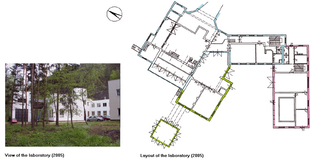 |
| The laboratory in 1964 | The Laboratory layout in 2005 |
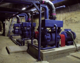 |
| The vacuum pump room |
The main duct and the wind tunnels are separated by quick-closing/opening valves (room 4). The largest wind tunnel for cascade research has a quick-slide-valve 600mm in diameter; and being pneumatically controlled it can open or close the vacuum storage in less than 0.5 sec. The other wind tunnels are attached to the same main duct; the smaller tunnels by a pipe 300mm in diameter, closed or opened by a similar pneumatically controlled slide valve. The modular wind tunnel has a quick- operating ball valve 600mm in diameter. All the quick-operating valves are secured by manually or electrically controlled slide valves of the same diameter. The compressed air for the control system has a pressure of 700 kPa; the compressor room is in the close neighbourhood of the valves.
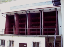
All wind tunnels are of the intermittent type, breathing the atmospheric air through a silicagel dryer, and pebble and cloth filters. Altogether 5 tons of active silicagel are placed in inclined beds 300mm thick with a permeable bottom (figure below). The total front area of the beds is 25 m2, so that the air velocity even at maximum airflow does not exceed 1 m/s, ensuring thus very low losses. The flue-solid particles from the dryer are caught by the filters – the pebble filter, 100mm thick, front area 24 m2, and the cloth filter made of firon. Even in the filters the velocity is less than 1 m/s. From the filters the air enters the inlet chamber (room 3). Entrances to all wind tunnels can be individually closed, to prevent sucking air into the inlet chamber through the idle wind tunnels, as well as to close the wind tunnels during the silicagel regeneration (i.e. drying). The process of silicagel regeneration is carried out by hot air, heated up to160 oC by an electric oven, and since 2005 it is fully automatic. During this period, as well as, during the time the Laboratory is out of operation, the air entrance is closed by perfectly sealed and insulated entrance gates (figure below).
 |
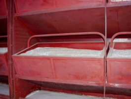 |
| Inlet gate with the silica gel dryer | Silica gel beds in the dryer |
| content: | Martin Luxa |
| designer & administrator: | David Šimurda |
